Interface and workflow
SRS NX is organised into three zones: the toolbar at the top, the PROJECT sidebar on the left, and the central tabbed panel. This page describes each and the full sequence of a project.
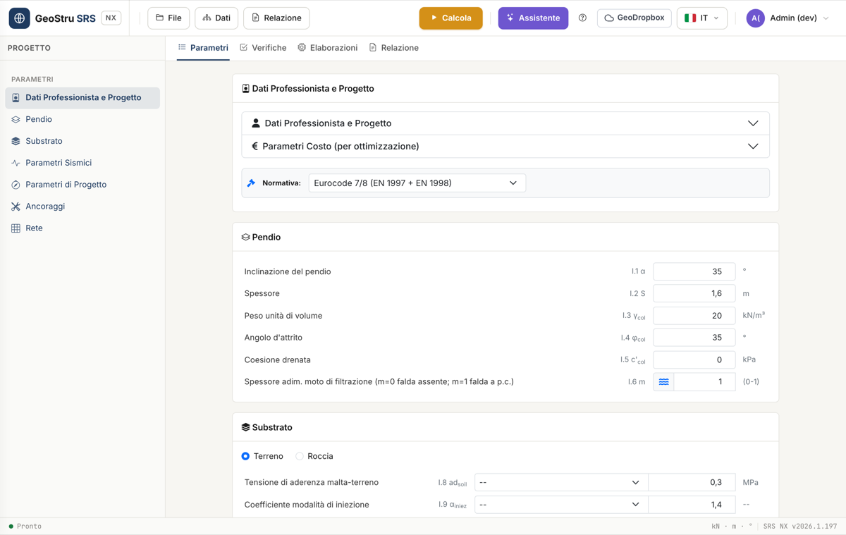
The toolbar
- File — New, Save, Open (
.srsproject). - Data — quick links to the sidebar sections (Professional Data, Slope, Substrate, Seismic Parameters, Design Parameters, Anchors, Mesh).
- Report — exports the report as Word (DOCX), PDF or DOC. Enabled only after a calculation with results.
- Calculate — the highlighted button, runs the full calculation (equivalent to step 3 "Start" in the Design Parameters card).
- Assistant — opens the AI chat.
- ? — opens the help modal, with a link to this manual.
- GeoDropbox — saves and retrieves projects from the suite's cloud storage.
- Language selector and user menu with your credit balance.
The PROJECT sidebar
Lists the seven input sections, in the order they appear in the Parameters tab: Professional Data and Project, Slope, Substrate, Seismic Parameters, Design Parameters, Anchors, Mesh. Clicking one scrolls straight to that section.
The four tabs
Parameters
All input data, organised into the seven sections above. Professional Data and Project is a collapsible card with your details, the project title, site coordinates and an optional descriptive image; it also holds the Cost Parameters accordion, used to estimate the cost of the intervention. This is also where you choose the reference design code (Eurocode 7/8, NTC 2018, or User for custom partial factors).
Design checks
Appears after a calculation. Shows FS₀, FS_des, the ΔFS increase, the outcome of the six checks R.2–R.7, a configuration summary (spacing, length, inclination, diameters) and the number of anchors/drilling metres per 100 m². See Design checks.
Elaborations
The intermediate calculation steps (E.1–E.28): volumes, forces, bar and mortar resistances, anchor geometry, reduction coefficients. Useful for checking a single step or comparing against a manual calculation.
Report
The starting point for generating the document; the actual export is triggered from the toolbar's Report menu. See Report and exports.
The full workflow
- Slope and substrate — enter the overburden geometry and geotechnical parameters, choose soil or rock. See Slope and substrate.
- Seismic action (optional) — set K_h if the site is seismic. See Seismic action.
- Calculate FS₀ — the slope's current safety factor, without any intervention.
- Set FS_des — the safety factor the intervention must reach.
- Nail and grid — pick the anchor (catalog or manual) and the grid spacing. See Nails and anchors.
- Facing mesh — mesh, wire, resistances. See Facing mesh.
- Calculate — SRS determines the required anchor tension and runs the six resistance checks.
- Read the Design checks — confirm all six are satisfied; if one fails, the card shows a hint on what to change.
- Report — export the calculation document.
FS₀ must be calculated before FS_des
The full calculation (Start/Calculate) requires FS₀ to already be computed: if you change the slope parameters after computing it, recalculate it before proceeding.
Found an error on this page? Let us know or open a Pull Request.