Design checks
After Calculate, the Design checks tab summarises the safety factors and the outcome of the six anchor resistance checks. This page explains what each one compares and how to read them.
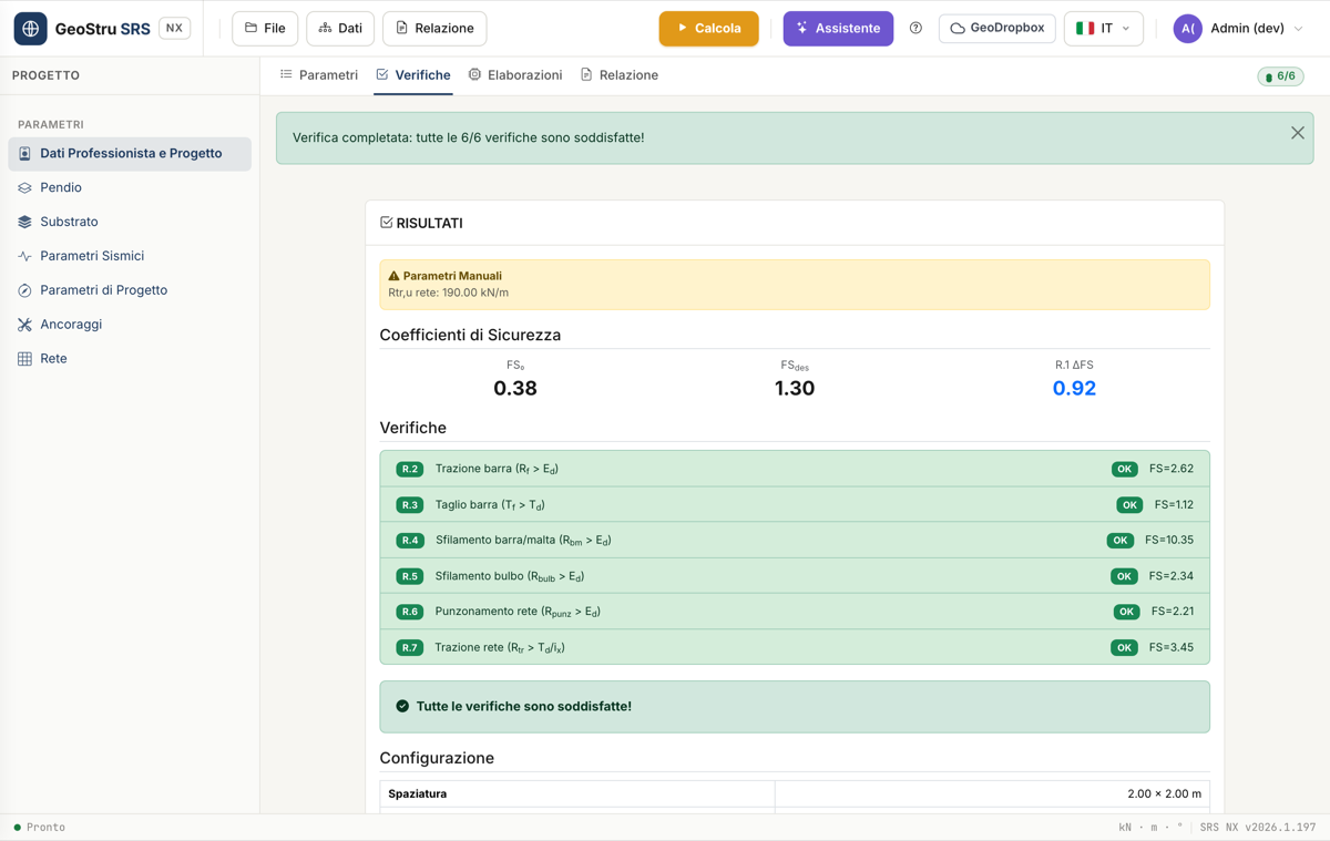
Safety factors
- FS₀ — the slope's safety factor before the intervention (computed in step 1 of the Design parameters card).
- FS_des — the design safety factor, the target you chose.
- R.1 ΔFS — the increase achieved:
ΔFS = FS_des − FS₀.
From FS_des, SRS derives the tension force A each anchor must provide to bring the slope from FS₀ to FS_des, accounting for the anchor's inclination β relative to the slope. This force, multiplied by the design-code coefficient γ_Q1, is the design E_d (tension) and T_d (shear) demand used in every check below.
The six checks (R.2–R.7)
| Code | Check | Comparison |
|---|---|---|
| R.2 | Bar tension | R_f > E_d |
| R.3 | Bar shear | T_f > T_d |
| R.4 | Bar/mortar slip | R_bm > E_d |
| R.5 | Bulb slip | R_bulb > E_d |
| R.6 | Mesh punching | R_punz,des > E_d |
| R.7 | Mesh tension | R_tr,des > T_d / i_x |
Each check is satisfied when the resistance exceeds the demand, and
shows its own safety factor FS = resistance / demand.
R.2 — Bar tension
Compares the bar's maximum tension resistance R_f (from the diameter φ_b, the yield strength f_yk and the coefficient γ_s) with the design tension demand E_d. If not satisfied: increase the bar diameter or use steel with a higher f_yk.
R.3 — Bar shear
Compares the bar's shear resistance T_f (derived from R_f with the von
Mises criterion, T_f = R_f / √3) with the design shear demand T_d. If
not satisfied: increase the bar diameter, the grid spacing (i_x, i_y), or
use steel with a higher f_yk.
R.4 — Bar/mortar slip
Compares the maximum bar-mortar bond R_bm (from the mortar's design bond strength f_bd and the length L_a) with E_d. If not satisfied: increase the anchor length, the drilling diameter, or the mortar strength (R_ck).
R.5 — Bulb slip
Compares the bulb pull-out resistance from the substrate R_bulb (from the bulb's collaborating length L_b, the substrate-mortar bond stress τ_sub, the drilling diameter, and the reduction coefficients ξ_a4 and γ_Rap) with E_d. If not satisfied: increase the anchor length, the drilling diameter, or the number of geotechnical investigation profiles (reduces ξ_a4).
R.6 — Mesh punching
Compares the mesh's design punching resistance R_punz,des with E_d. If not satisfied: choose a mesh with a higher punching resistance.
R.7 — Mesh tension
Compares the mesh's design tension resistance R_tr,des with the shear demand distributed over the horizontal spacing, T_d / i_x. If not satisfied: choose a mesh with a higher tension resistance or reduce the i_x spacing.
A hint for every failed check
When a check fails, the card automatically shows a suggestion of which parameter to change — the same ones listed above.
Anchors per 100 m²
- R.8 Count — how many anchors are needed per 100 m² of mesh:
N_tot = round(100 / (i_x · i_y)). - R.9 Total drilling length — the corresponding drilling metres:
L_tot = N_tot · L_a.
These are the two figures to report in a preliminary bill of quantities for the intervention.
Estimated cost
If you filled in the Cost parameters (drilling €/m, steel €/kg, mortar €/m³, mesh €/m²) in the Professional Data and Project section, the Design checks tab also shows an estimate of the total cost per 100 m² of mesh — the sum of drilling cost, bar steel cost, grouting mortar cost and mesh cost.
Found an error on this page? Let us know or open a Pull Request.