Planar sliding
Stability analysis for sliding along a single plane. It applies when a discontinuity has a dip direction close (± 20°) to that of the slope face and a dip lower than that of the face (the daylighting condition): the overlying wedge can slide along the joint. The analysis is carried out using limit equilibrium.
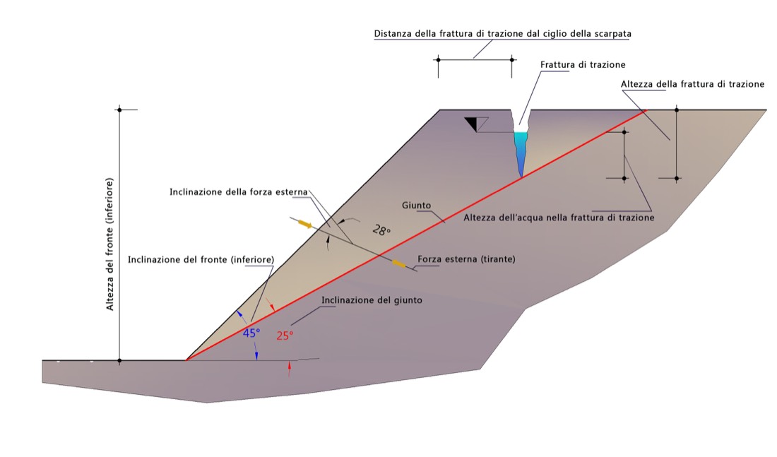
Figure 1 — Limit equilibrium conditions of a slope affected by a joint, with a planar upper face.
Two failure geometries are assumed: absence or presence of an open tension crack in the upper part of the slope.
Notation
| Symbol | Quantity |
|---|---|
| \(A\) | length of the sliding plane |
| \(W\) | weight of the detaching wedge |
| \(\psi\) | inclination of the joint (sliding plane) |
| \(H_f\) | height of the face |
| \(\alpha\) | inclination of the face |
| \(\gamma\) | unit weight of the rock |
| \(\gamma_w\) | unit weight of water |
| \(H_w\) | height of water on the plane |
| \(a_g\) | maximum horizontal acceleration |
| \(F_H\) | seismic inertia force |
| \(U\) | water thrust on the plane |
| \(V\) | water thrust in the tension crack |
| \(Q\) | external forces, inclined by \(\theta\) |
| \(z\) | height of the tension crack |
| \(b\) | distance of the tension crack from the crest |
| \(z_w\) | height of water in the tension crack |
Base case — absence of a tension crack
In the simplest case (no tension crack, no external forces), equilibrium is expressed by the factor of safety:
where \(c\) and \(\varphi\) are the cohesion and friction angle of the joint.
The length of the plane and the weight of the wedge are obtained from the geometry:
General case — water, seismic action and external forces
In the presence of water in the joints and external actions, the quantities involved are:
Seismic inertia force (with \(S = 1\), since these are rock formations):
Water thrust on the plane (drained slope, triangular distribution):
The factor of safety becomes:
The external forces \(Q\) inclined by \(\theta\) (surcharges, interventions) enter the equilibrium through their components relative to the plane: the normal component increases (or reduces) the normal stress and hence the resisting frictional contribution, while the tangential component adds to the driving or resisting forces depending on its direction.
Tension crack
When a tension crack of height \(z\) is present at a distance \(b\) from the crest, with water of height \(z_w\), the water thrust in the crack is added:
and the factor of safety includes the \(V\) terms:
with the length of the plane reduced by the presence of the crack.
Impeded drainage (retention basin)
The expression for water thrust shown above applies to a drained slope in the case of intense rainfall. When drainage at the toe is impeded — for example in a retention basin — the pressure on the joint is greater (a distribution close to the full hydrostatic case):
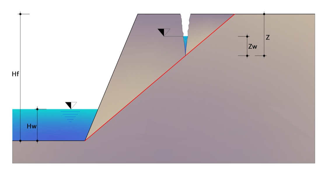
Figure 2 — Retention basin, significant quantities.
Inclined upper face
When the sliding plane affects an upper face that is slightly inclined by an angle \(\beta\), the design height becomes the overall height \(H_p\) (lower face + upper face) and the expressions for \(A\) and \(W\) adapt to the new geometry; in the presence of a tension crack, the same considerations as in the previous case apply. Here too, if drainage at the toe is impeded, the water thrust on the joint takes the impeded-drainage form.
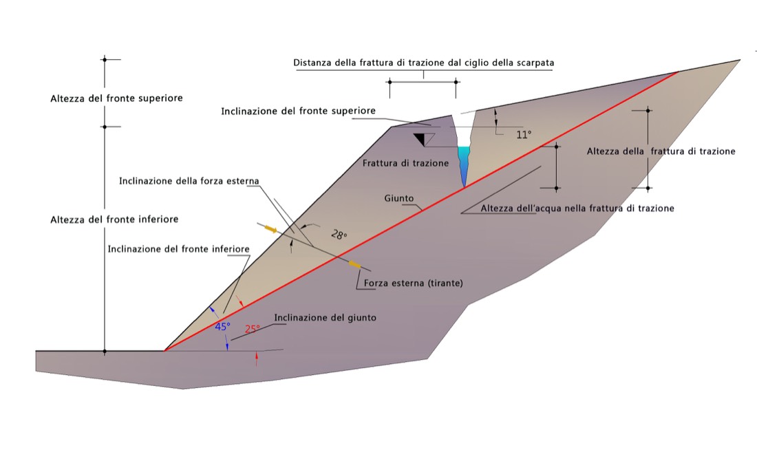
Figure 3 — Limit equilibrium conditions of a slope affected by a joint, with an inclined upper face.
Two-joint kinematics
For the sliding of a wedge formed by two discontinuities, see Sliding 3D. For the design of interventions (rock bolts, anchors, meshes) on planar failure with code-based verification according to NTC 2018 / EC7, please refer to RockPlane NX.
Found an error on this page? Let us know.