Sliding 3D — wedge sliding
One of the most frequent cases in practice. When the rock mass contains several discontinuity sets with different orientations, two planes can intersect to form a tetrahedral rock wedge that gives rise to a three-dimensional failure mechanism. This is the typical situation at the origin of many failures of slopes and rock faces.
The motion associated with sliding can occur:
- along the line of intersection of the two planes — provided that this line has an inclination lower than that of the face and a dip direction equal to that of the face;
- on a single plane, depending on the direction of motion and the attitude of the discontinuities.
Calculation scheme
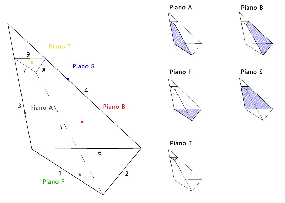
Figure — Scheme of the three-dimensional wedge and of the planes that define it.
Calculating the factor of safety
The calculation, under the three-dimensional conditions typical of the model, involves determining, in order:
- Attitude unit vectors of each plane: normal to plane A, to plane B, to the possible upper plane S, to the plane of the face F, and to the possible plane of the tension crack T. In the presence of external forces (pseudo-static, stabilising), the unit vectors of their directions of action are also defined.
- Vectors of the lines of intersection between the planes, whose attitude is given by the cross product of the respective normal unit vectors.
- Linear dimensions and rock volume of the wedge.
- Areas of planes A, B and T, in order to compute the contributions of frictional and, where applicable, cohesive strength.
- Coefficients of the effective normal relations.
- Weight of the mobilised wedge.
- Water thrusts on the possible tension crack, on planes A and B, and possibly on the face.
- Kinematic checks to define the possibility of three-dimensional sliding and the type of sliding (along the intersection or on a single plane).
- Additional forces, both resisting (stabilising) and destabilising (seismic conditions), and finally the factor of safety.
When to use which tool
Rock Mechanics NX recognises the wedge kinematics and computes its safety starting from the survey. For the design of interventions (rock bolts, anchors, rockfall meshes) and for dedicated parametric analyses, please refer to RockPlane NX and to the Geoapp applications (3D Wedges).
Found an error on this page? Let us know.