Discharge system
The discharge device determines the outflow from the storage facility and therefore the attenuation. HID implements eight of them.
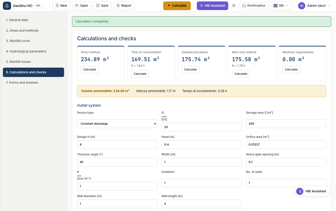
The available devices
| Device | Parameters | Law |
|---|---|---|
| Constant flow | Qu,lim | Q constant, independent of the head |
| Thomson weir | angle θ | Q ∝ tan(θ/2) · h5/2 |
| Bazin weir | width | Q ∝ L · h3/2 |
| Crump weir | width | Q ∝ L · h3/2 |
| Circular submerged orifice | area A | Q = 0.6 · A · √(2gh) |
| Sluice gate | opening, width | Q = 0.6 · a · L · √(2gh) |
| Constant infiltration | K, gradient | Q ∝ K · i · area |
| Infiltration well | number, diameter, length | function of the head and of the infiltrating area |
How the discharge limit is chosen
This is where mistakes are most frequent, so HID follows a single order:
- If the regulation imposes it, that value applies. In Lombardia it is derived from area, runoff coefficient and hydraulic criticality zone.
- Otherwise you choose it. But the "constant outflow" field only makes sense for a constant-flow discharge: for a submerged orifice, a weir or a sluice gate, what applies is the flow of the device at the design head.
Warning
Point 2 is why, when you change the discharge type, the required volume can change considerably: the reference flow is no longer the one you typed in the field, but the one the device actually discharges.
Design head
For devices that depend on the head, the value H you enter is the maximum effective water head. The corresponding flow is shown below the block as flow at the design head.
Found an error on this page? Let us know.