Ultimate load
MP NX computes the ultimate vertical load with static formulae, for each investigation vertical and each combination, then applies the ξ factors and the γR factors. This page explains the choices in the Pile card and how to read the Ultimate load tab.
Net ultimate load
In compression:
Q = Qp + Qs − W − Qneg
with Qp the base resistance, Qs the shaft resistance, W the pile weight and Qneg the adhesion of the layers in negative skin friction. In tension the base does not work: Q = Qs + W.
Base resistance
Qp = A·(σ′v·Nq + c·Nc), with σ′v the effective vertical stress at the toe, including the surcharge qpc. Nq and Nc depend on the Method for Nq:
| Method | Nq | Nc |
|---|---|---|
| Berezantsev | function of φ and L/D; for D > 0.8 m interpolation on L/D | (Nq − 1)/tan φ; 9 for φ = 0 |
| Berezantsev (L/D = 32) | 0.48·exp(4.97·tan φ) | as above |
| Terzaghi | Terzaghi's formula (1943) | (Nq − 1)/tan φ, minimum 5.7 |
| Janbu | function of φ and of the relative density Dr (ψ = 60° + 0.45·Dr) | (Nq − 1)/tan φ; 5.74 for φ = 0 |
| Hansen | exp(π·tan φ)·tan²(45° + φ/2) with shape and depth factors | with the same factors; 5.14 for φ = 0 |
| Vesic | function of φ and of the rigidity index Ir = 1.7·Dr | (Nq − 1)/tan φ |
| Nq utente (user value) | the value of the Nq assigned field | (Nq − 1)/tan φ; 9 for φ = 0 |
With Janbu and Vesic the Dr field appears, the relative density in %. The full formulae and the control values at φ = 30° are in the validation document.
The Friction angle for the shaft resistance field corrects φ before the calculation: φ, φ − 3° (bored), ¾ φ + 10° (driven) or (φ + 40°)/2. The corrected angle also enters Nq: in Bowles' example 16.10, φ = 32° becomes 34° at the toe.
Shaft resistance
Qs = π·D·Σ (K·tan δ·σ′v,mean + α·c)·t, summed over the layers of thickness t.
- Earth pressure coefficient K: 0.5; 1; 1 − sin φ; 1 − tan² φ; or User value.
- Soil-pile friction angle: δ = φ, ⅔ φ, ¾ φ, 20° or 25°.
- α and c (or cu) come from the layer.
In rock layers the frictional term is zero and τ = α·Rcᵏ. The adhesion above the founding plane of the footing is removed. For tapered driven piles the taper factor Fw applies.
K is computed with the unreduced φ
With K = 1 − sin φ or 1 − tan² φ the program uses the friction angle of the layer, not the one reduced by the M factors or corrected for driving. It is the behaviour of the desktop program, declared in the validation document.
From Q to Rk and Rd
For each combination the program computes Qp and Qs on all the verticals, then:
- takes minimum and mean, and with ξ3 and ξ4 obtains Rk,p and Rk,s;
- divides by γb and γs and subtracts the weight: Rd = Rk,p/γb + Rk,s/γs − W;
- compares with the action: FSv = Rd/|Ed,v|.
The weight W is that of the first vertical. The factors are described in Loads, combinations and design code.
Ultimate lateral load (Broms)
Hmax is computed with Broms' method, in Viggiani's formulation: cohesive soils (with cu) and cohesionless soils (with Rankine's Kp), free or fixed head according to the Head restraint in General data. The mechanism depends on the ultimate moment of the section My and is shown in the table as Short pile, Intermediate pile or Long pile.
Where My comes from:
- if you enter My in the Materials and reinforcement card, your value prevails;
- if My = 0 and the FEM analysis is enabled, the ultimate moment of the reinforced section at N = 0, computed by the program, is used;
- for the tubular micropile with My = 0 the moment of the composite tube + grout section is used;
- if My = 0 and the FEM is off, the lateral check is not performed.
The design resistance is Rd,h = Rk,h/γT and the check FSh = Rd,h/Ed,h.
Seismic correction
With a/g > 0 in the Seismic action card the ultimate load is reduced with one of three methods:
| Method | Correction |
|---|---|
| Vesic | φ reduced by 2° |
| Okamoto | base and cohesive shaft term multiplied by 1 − a/g |
| Sano | φ reduced by atan(a/(g·√2)) |
Vesic and Sano restart from the unreduced angle φ: with the M2 factors the reduction of φ is not cumulated. This too is declared in the validation document.
Reading the Ultimate load tab
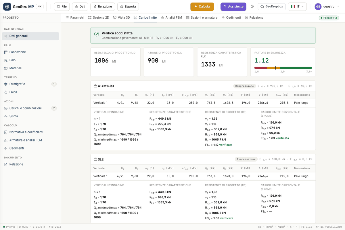
At the top is the outcome, Check satisfied or Check NOT satisfied, with the Governing combination, that is the one with the lowest safety factor. The four tiles report Rd, Ed, Rk and the Safety factor on a scale from 1 to 3.
Then comes one card per combination. The header says whether it is in Compression or Tension and reports Ed,v and Ed,h. The table has one row per vertical:
| Column | Meaning |
|---|---|
| Nq, Nc | bearing capacity factors used |
| φp, cp | friction angle and cohesion at the toe, after corrections and factors |
| σ′v,p | vertical stress at the toe |
| Qp, Qs, W | base, shaft, pile weight |
| Q | net ultimate load; in brackets the negative skin friction subtracted |
| Hmax, Mechanism | Broms' ultimate lateral load and mechanism |
Below the table, four groups: Investigation verticals (n, ξ3, ξ4, minimum, mean and maximum of Qp and Qs), Characteristic resistances, Design resistances with γb, γs and FSv, and Ultimate lateral load (Broms) with FSh. Any messages from the calculation appear at the bottom.
Found an error on this page? Let us know or open a Pull Request.