FEM analysis
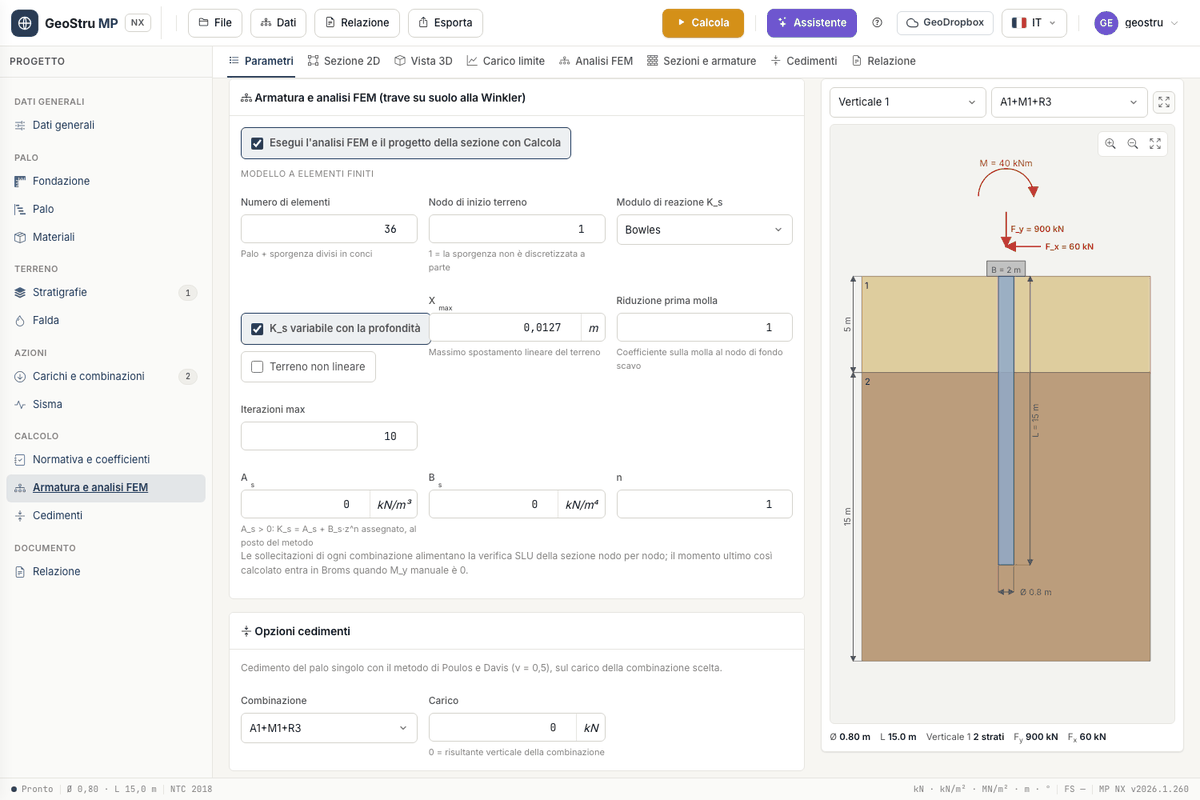
The FEM analysis computes the internal forces along the pile for horizontal forces, moments and vertical forces applied at the head or at any elevation. The pile is a beam on Winkler elastic soil: beam elements with constant stiffness E·J and, at each node in the ground, a horizontal spring.
Enabling the analysis
In the Reinforcement and FEM analysis card tick Run the FEM analysis and the section design with Calculate. With the tick, Calculate also runs the FEM and the section check, and charges 5 more credits. If the analysis produces no results the FEM credit is not charged and the geotechnical calculation remains valid; the reason appears in the messages.
The model
| Field | Meaning |
|---|---|
| Number of elements | segments the pile is divided into, protrusion included |
| First soil node | first node with a spring; 1 = the protrusion is not discretised separately |
| Subgrade modulus Ks | Bowles or Chiarugi-Maia |
| Ks varying with depth | with Bowles, Ks = As + Bs·z; unticked, constant Ks |
| Non-linear soil | iteratively removes the springs that are no longer effective |
| Xmax | maximum linear soil displacement [m] |
| First-spring reduction | factor on the spring at the first soil node |
| Max iterations | maximum number of cycles of the non-linear calculation |
| As, Bs, n | assigned Ks: with As > 0, Ks = As + Bs·zⁿ replaces the method |
The stiffness of each spring is Ks(z)·D times the tributary length of the node, with half a step at the ends. The elastic modulus of the pile is that of the concrete class in the materials archive; the second moment of area is J = π·D⁴/64, or the J assigned. The axial force comes from the self-weight and the vertical forces.
Modulus of subgrade reaction Ks
- Bowles: Ks = As + Bs·z, with As = 40·(c·Nc + ½·γ·D·Nγ) and Bs = 40·γ·Nq, in kN/m³, with Hansen's bearing capacity factors. It is computed automatically from the layer parameters.
- Chiarugi-Maia: kh from the oedometric modulus Eed, Poisson's ratio ν of the layer and the pile-soil relative stiffness. Fill in Eed and ν in the layer properties.
- Assigned: enter As, Bs and n. Use it for a Ks from tests or from the literature.
Linear and non-linear
In the linear calculation all springs work, in tension too. With Non-linear soil the program repeats the solution and removes the springs with a negative displacement (in tension) or one larger than Xmax, up to the maximum number of iterations.
Reading the FEM analysis tab
Choose the combination from the drop-down. At the top the maxima: Mmax, Tmax, Max displacement and Max pressure. Then the five Internal-force diagrams, each with its maximum value and zoom controls:
- Soil pressures (p = Ks·y)
- Spring reactions
- Bending moment
- Shear
- Deflection
The Results per node table reports, for each node: elevation z, N, M, T, rotation, displacement, pressure p, Ks and reaction R. A load with z > 0 is applied to the node nearest to the given elevation: check in the table where it ended up.
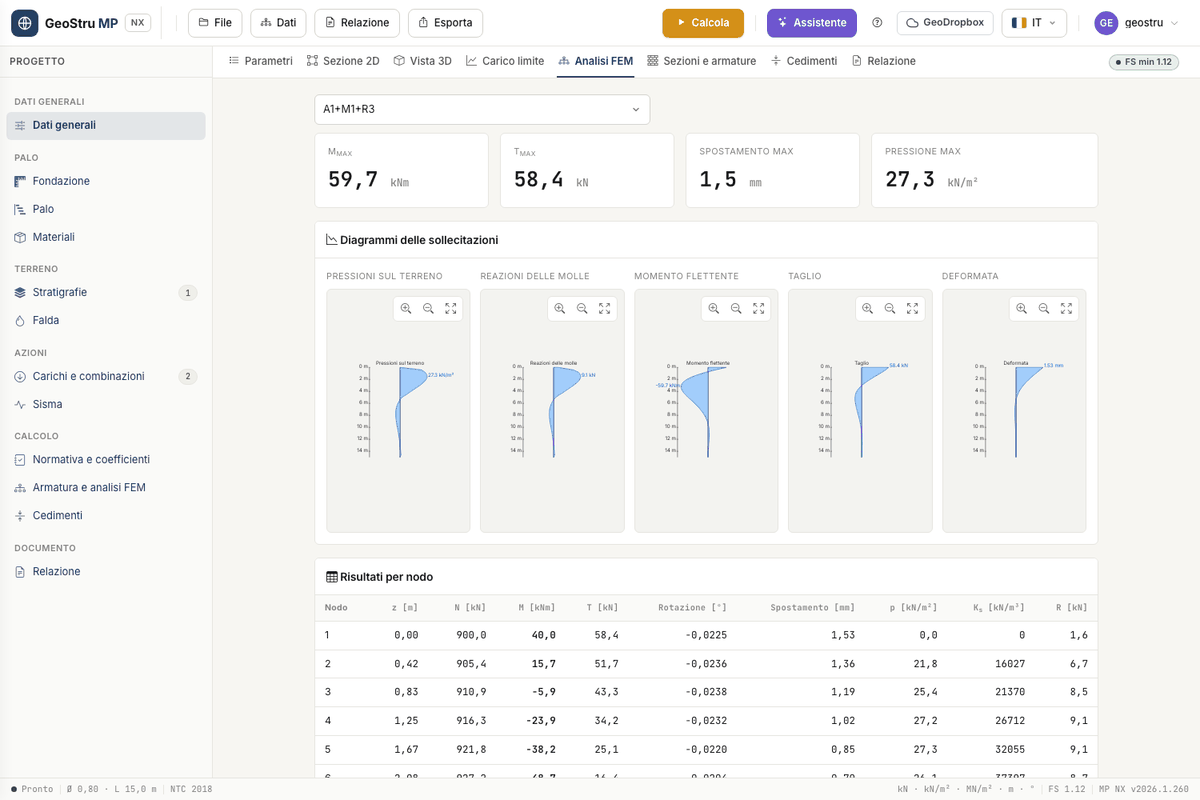
The internal forces of each combination feed the section check node by node. The diagrams also go into the DXF drawing and the report.
Limits of the model
Large displacements
The Winkler model captures neither the interaction between springs nor soil yielding, beyond the removal of springs. For piles with large displacements you need analyses with p-y curves or continuum models, which MP NX does not offer.
The analysis concerns the single pile: it does not account for group effects. The structural check that follows holds for the circular reinforced-concrete section: the FEM accepts an assigned J for other sections, the ULS check remains that of the circular section of diameter D.
Found an error on this page? Let us know or open a Pull Request.