Loads, combinations and design code
Actions are in the Loads and combinations card, factors in the Code and partial factors card. The design code is chosen in General data.
Loads at the head and at the nodes
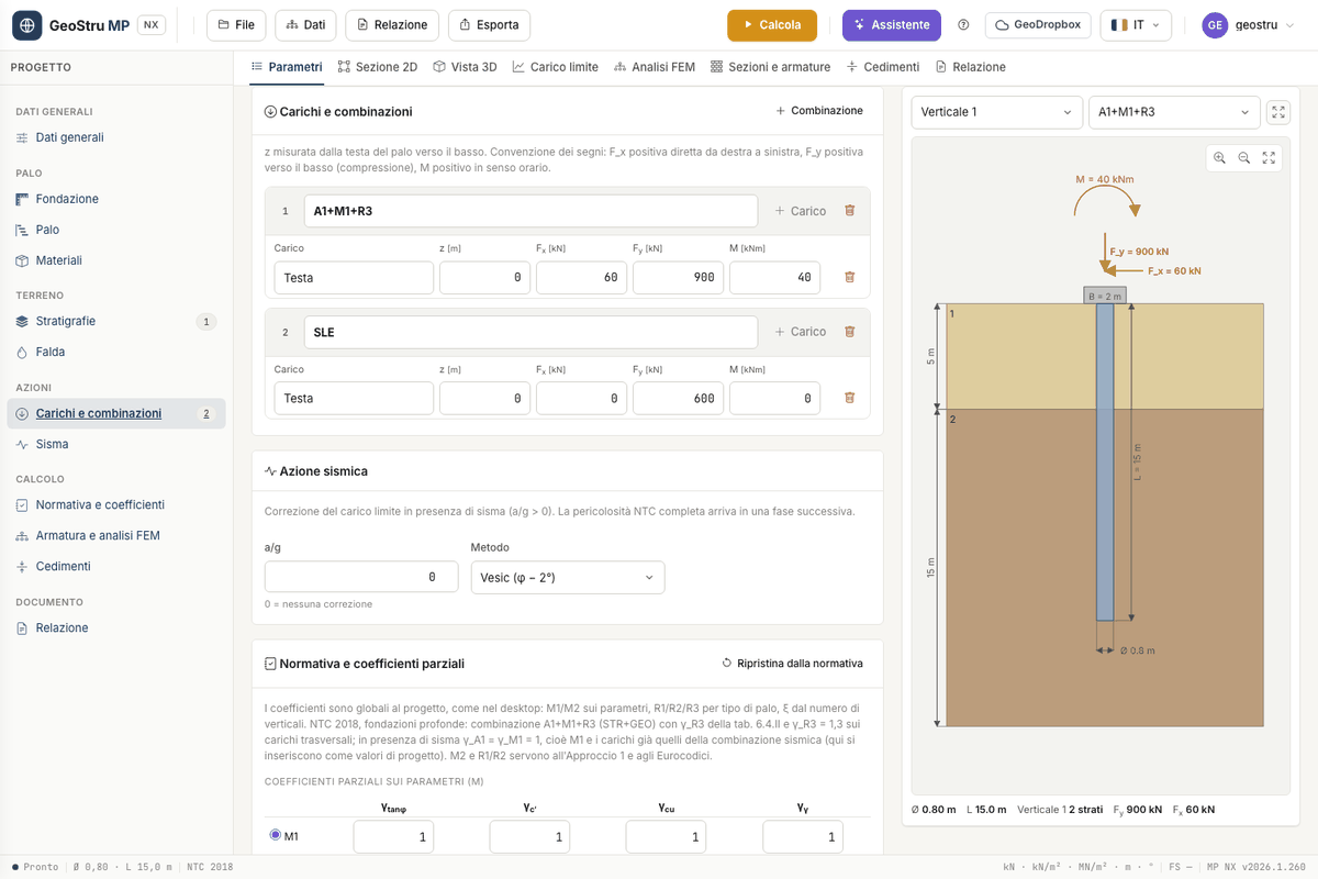
A combination is a named list of loads. Combination adds one, Load adds a row to the combination. Each load has:
| Column | Meaning |
|---|---|
| z | elevation of the point of application, measured downwards from the pile head [m] |
| Fx | horizontal force [kN] |
| Fy | vertical force [kN] |
| M | moment [kNm] |
With z = 0 the load is at the head. A load with z > 0 is applied along the shaft: in the FEM model it goes to the nearest node. It is used, for instance, for thrusts on a free length above ground.
For the geotechnical check the program sums the loads of each combination: Ed,v is the vertical resultant, Ed,h the horizontal one. If Ed,v is negative the combination is in tension: the base does not work and Rd = Rk,s/γs + W.
Loads are design values
MP NX does not multiply the actions by γF. Enter loads already combined and factored, as they come out of the structural analysis. Names such as "A1+M1+R3" or "SLE" are labels: they do not change the factors.
Sign convention
It is that of the MP desktop program, and the drawing follows it:
- positive Fx acts from right to left;
- positive Fy acts downwards (compression);
- positive M is clockwise.
The action scheme is drawn above the pile head, with the moment arc above the two arrows. Check the direction of the loads there before calculating.
Design code
In the Design code (GEO) field choose among:
- NTC 2018 — D.M. 17/01/2018;
- Eurocodice 7 — EN 1997-1 (Eurocode 7);
- EN 1997-1 — Romanian national annex;
- Classical theory (global factors).
When you change the code, the factors card reloads with the default values. Factors belong to the project: they apply to all combinations.
The NTC 2018 approach for deep foundations
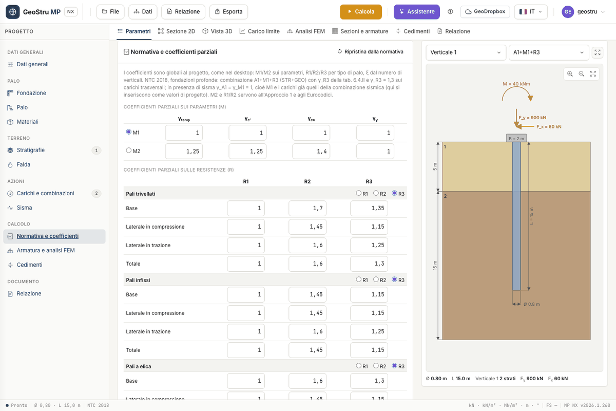
For piles NTC 2018 prescribes combination A1+M1+R3: M1 factors (equal to one) on the soil parameters and γR3 from table 6.4.II on the resistances. With the default values:
| γR3 | Base γb | Shaft in compression γs | Shaft in tension | Total |
|---|---|---|---|---|
| Bored piles | 1.35 | 1.15 | 1.25 | 1.30 |
| Driven piles | 1.15 | 1.15 | 1.25 | 1.15 |
On transverse loads γT = 1.3. With seismic action γA1 = γM1 = 1: enter the loads of the seismic combination and keep M1. Sets M2 and R1/R2 serve Design Approach 1 and the Eurocodes.
Correlation factors ξ3 and ξ4
They depend on the number n of investigation verticals (NTC 2018, table 6.4.IV). The table in the card has columns n = 1, 2, 3, 4, 5, 7, 10; with n = 6 and n = 9 the program uses columns 7 and 10. With one vertical ξ3 = ξ4 = 1.70; with three, ξ3 = 1.60 and ξ4 = 1.48.
The characteristic resistance is computed separately for base and shaft: Rk = min(Qmean/ξ3, Qmin/ξ4). With User-assigned ξ the program ignores the table and uses the two values you enter.
Design resistance
Rd = Rk,p/γb + Rk,s/γs − W in compression. With Global factor on the ultimate load (General data) the "Total" factor is used on both. The check is FS = Rd/|Ed| ≥ 1. For the lateral load Rd,h = Rk,h/γT.
With the Classical theory ξ = 1 and the global factors are 2.5 on base and shaft; you find them in the Classical theory and other block, together with the k rock exponent.
Editable factors
All values in the card can be changed: the M1/M2 factors (γtanφ, γc′, γcu, γγ), the R1/R2/R3 sets per pile type, γT and the ξ table. The M1/M2 and R1/R2/R3 buttons choose the column applied. Reset from code reloads the defaults of the selected code.
The card also shows the Screw piles row, inherited from the code table: MP NX does not compute screw piles and that row is not used.
Seismic action
In the Seismic action card enter a/g and choose the method that corrects the ultimate load: Vesic, Okamoto or Sano. With a/g = 0 there is no correction. The three methods are described in Ultimate load. The full NTC seismic hazard is not part of MP NX: you obtain a/g separately.
Found an error on this page? Let us know or open a Pull Request.